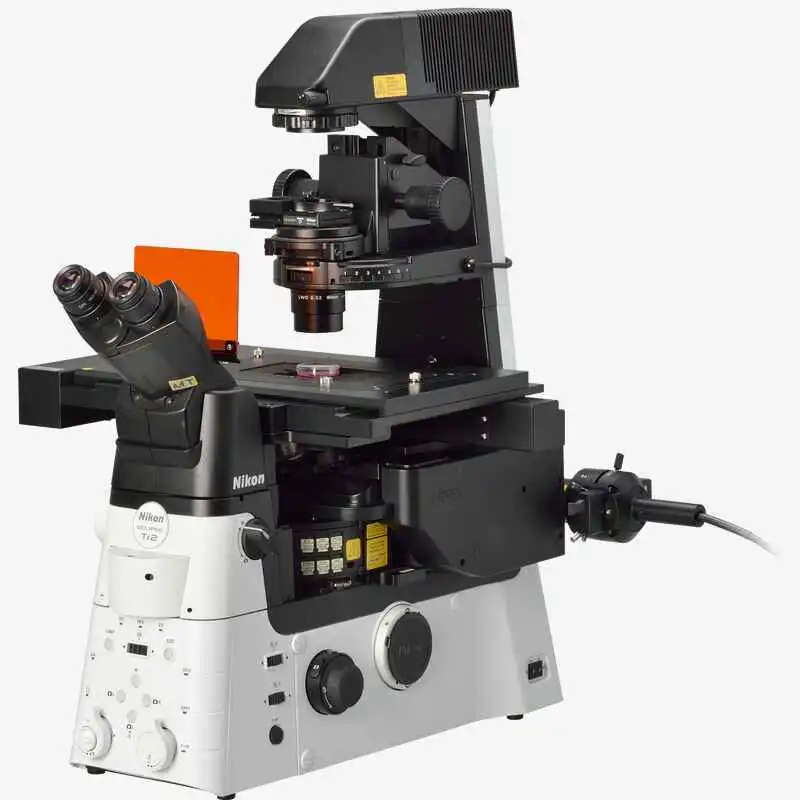
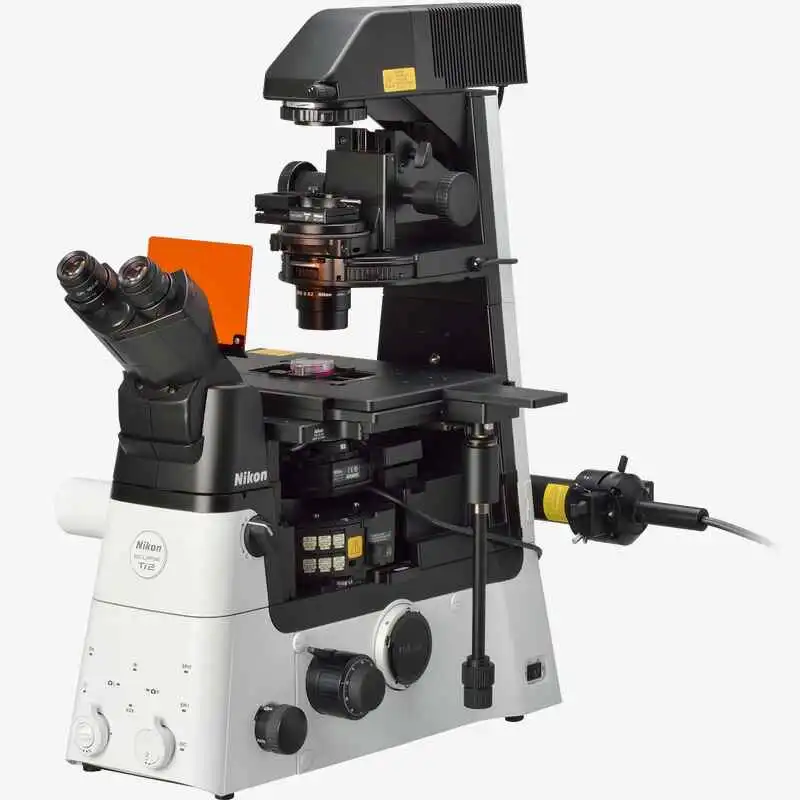
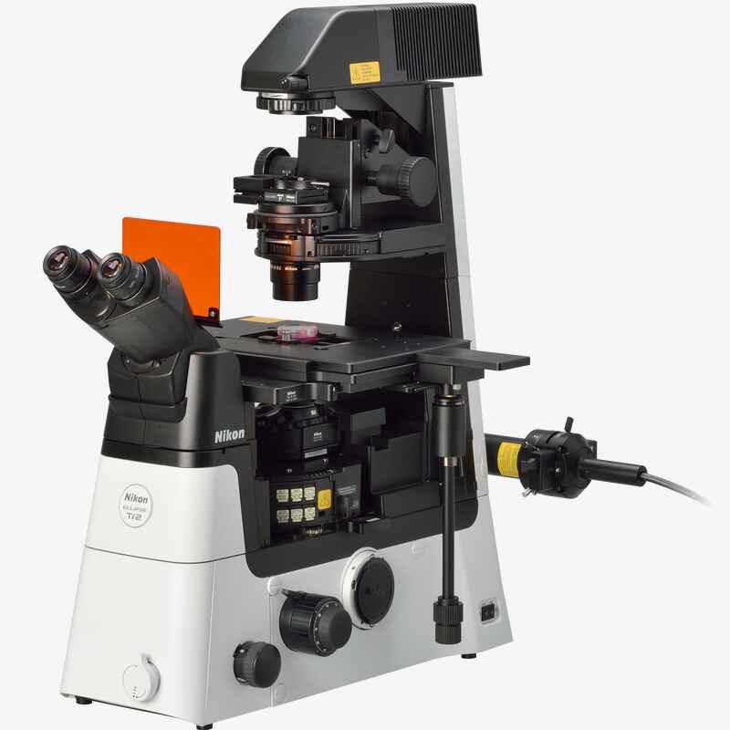
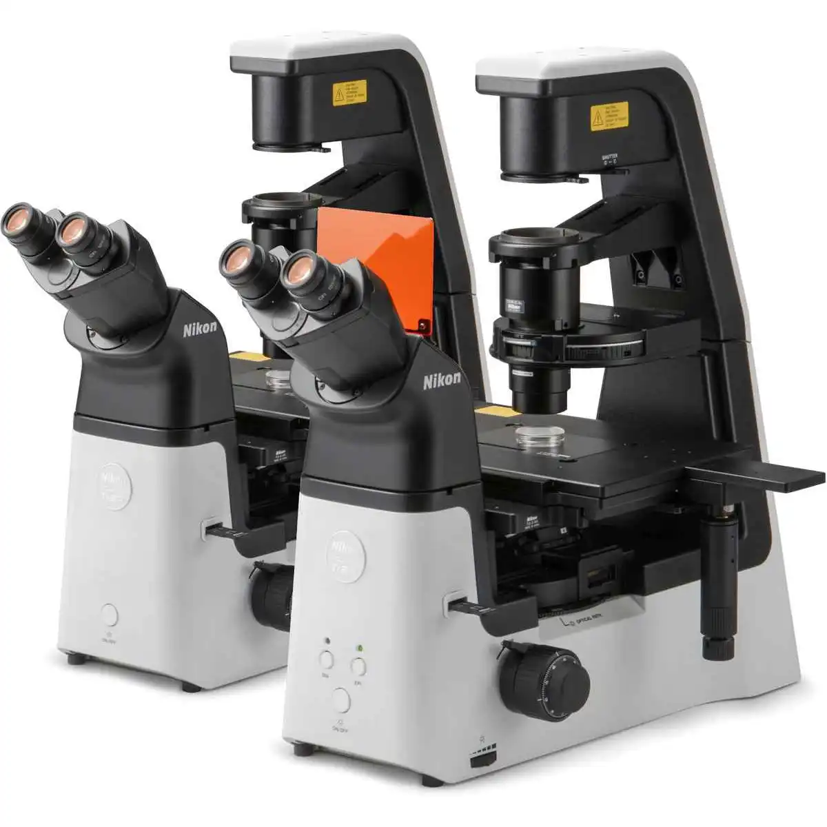
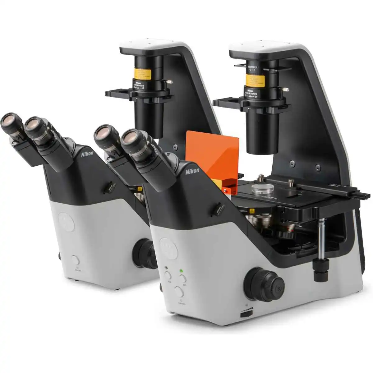
NIKON ECLIPSE Ti2-E
Motorized Research Inverted Microscope
Motorized and intelligent model for advanced imaging applications. Compatible with PFS, auto correction collar, and external phase contrast system. The base of choice for live-cell imaging, high-content applications, confocal and super-resolution.
The ECLIPSE Ti2-E inverted microscope delivers an unparalleled 25mm field of view (FOV) that revolutionizes the way you see. With this incredible FOV, the Ti2-E maximizes the sensor area of large-format CMOS cameras without making compromises, and significantly improves data throughput. The Ti2-E's exceptionally stable, drift-free platform is designed to meet the demands of super-resolution imaging while its unique hardware-triggering capabilities enhance even the most challenging, high-speed imaging applications. Furthermore, the Ti2-E's unique, intelligent functions guide users through imaging workflows by gathering data from internal sensors, eliminating the possibility of user errors. In addition, the status of each sensor is automatically recorded during acquisition, providing quality control for imaging experiments and enhancing data reproducibility.
In combination with Nikon's powerful acquisition and analysis software, NIS-Elements, the Ti2-E is a total innovation in imaging.
Key Features
Groundbreaking FOV
As research trends evolve towards large-scale, systems-level approaches, there is an increasing demand for faster data acquisition and higher throughput capabilities. Development of large-format camera sensors and improvements in the data processing capabilities of PCs have facilitated such research trends. The Ti2-E, with its unprecedented 25mm field of view, provides the next level of scalability, enabling researchers to truly maximize the utility of large-format detectors and future-proof their core imaging platform as camera technologies continue to develop at a rapid pace.
Bright illumination over a wide area
High-power LEDs deliver bright illumination across the Ti2's large field of view, ensuring clear, consistent results from demanding applications such as high-magnification DIC. Incorporation of a fly-eye lens design provides uniform illumination from edge to edge for quantitative high-speed imaging and seamless tiling of images in stitching applications.
:成贯仪器)

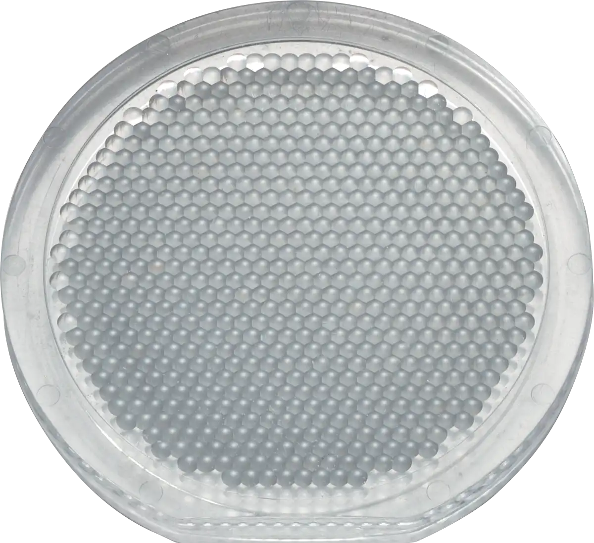
High-power LED illuminator Built-in fly-eye lens
A compact epi-fluorescence illuminator designed for large FOV imaging is equipped with a quartz fly-eye lens and provides high transmittance across a broad spectrum, including UV. Large diameter fluorescence filters with hard coatings deliver large FOV images with a high signal-to-noise ratio.:成贯仪器)

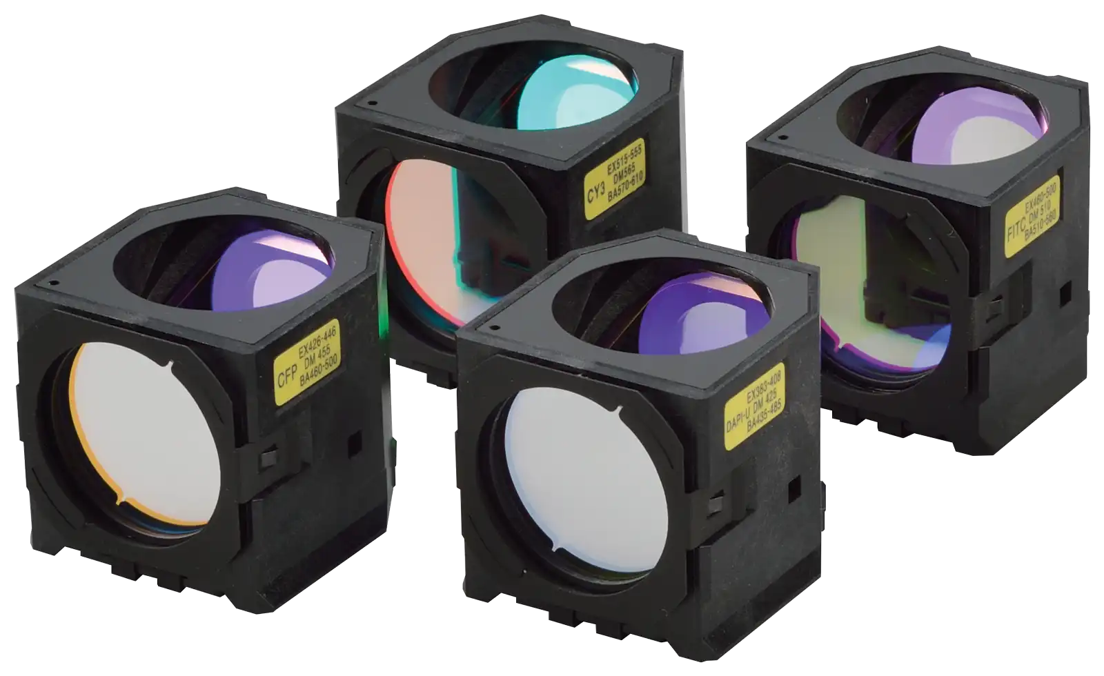
Large FOV epi-fl illuminator Large diameter fluorescence filter cubes
Large diameter observation optics
The diameter of the observation light path has been enlarged in order to achieve a field number of 25 at the imaging port. The resulting large FOV is capable of capturing approximately double the area of conventional optics, enabling users to gain maximum performance from large-format sensors such as CMOS detectors.
源:成贯仪器)

Enlarged tube lens Imaging port with large 25 field number
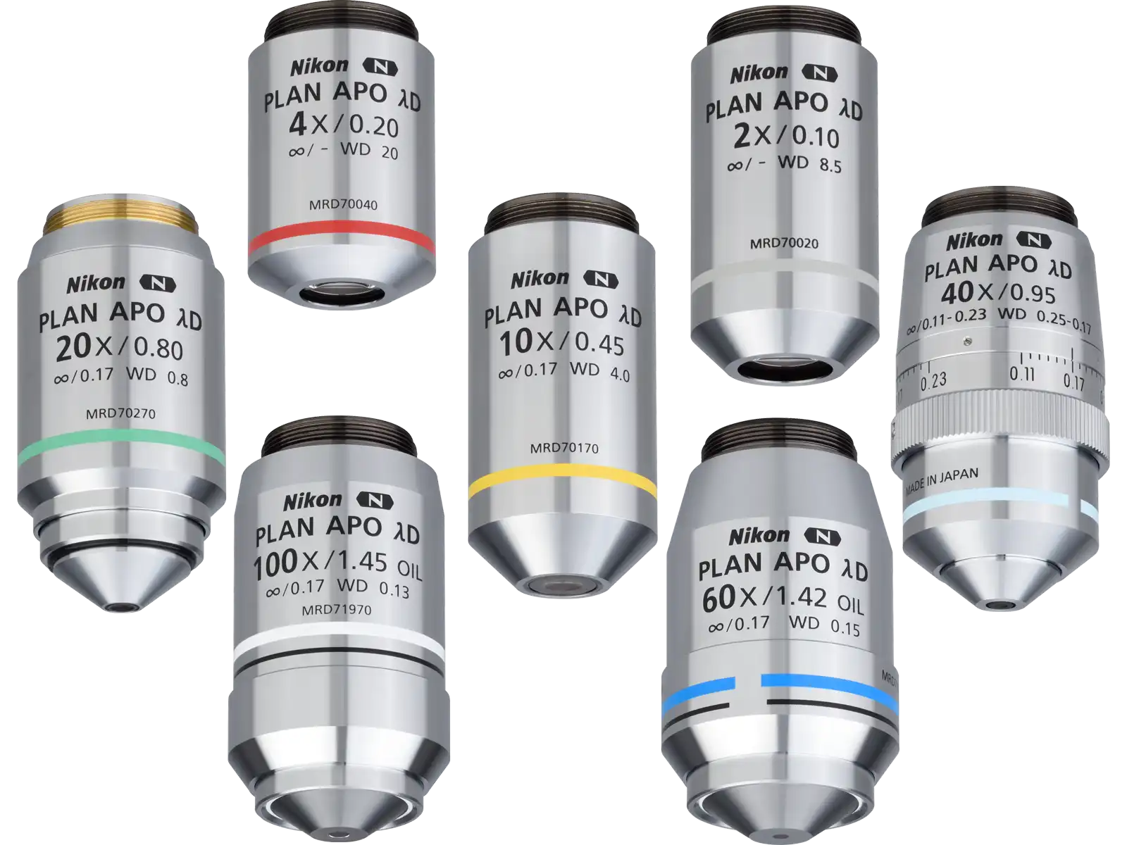
Objectives for large FOV imaging
Objectives with superior image flatness ensure high quality images from edge to edge. Utilizing the maximum potential of the OFN25 objective significantly accelerates data collection.
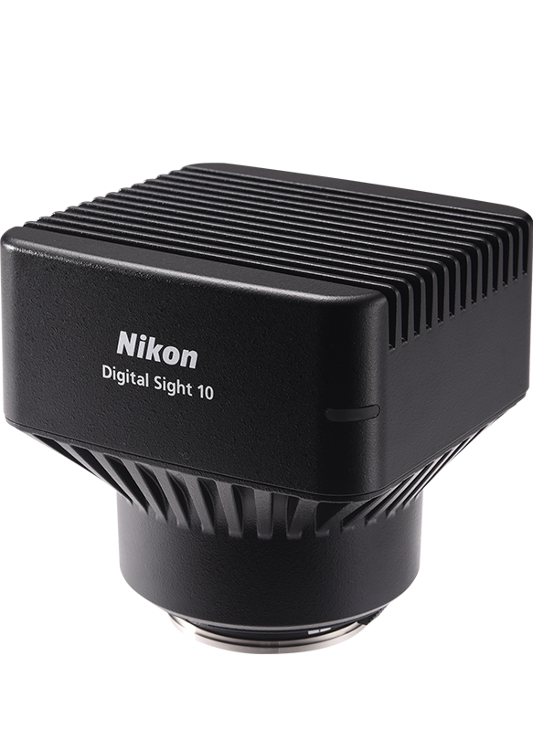
Cameras for large-volume data acquisition
Nikon's FX-format F-mount cameras Digital Sight 50M and Digital Sight 10 are equipped with CMOS image sensors optimized for research use, originally developed for professional D-SLR cameras. This allows high-speed and high-sensitivity live-cell imaging, enabling the best use to be made of the Ti2-E's large FOV.
(来源:成贯仪器)


Unsurpassed Nikon optics
Nikon's high-precision CFI60 infinity optics, designed for use with a variety of sophisticated observation methods, are highly regarded by researchers for their superb optical performance and solid reliability.
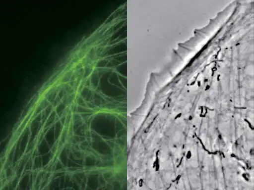
Apodized phase contrast
Nikon's unique apodized phase contrast objectives with selective amplitude filters dramatically increase contrast and reduce halo artifacts to provide detailed high-definition images.

Apodizedphase plate is incorporated in APC objectives BSC-1 cells captured with CFI S Plan Fluor ELWD ADM 40XC objective
External phase contrast
The motorized external phase-contrast system enables users to combine phase contrast with epi-fluorescence imaging without compromising fluorescent light transmission by bypassing the need to use phase-contrast objectives. For example, very high NA, liquid immersion objectives can be used for phase-contrast imaging. Using this external phase contrast system, users can easily combine phase contrast with other imaging modalities, including weak-fluorescence imaging such as TIRF and laser tweezer applications.
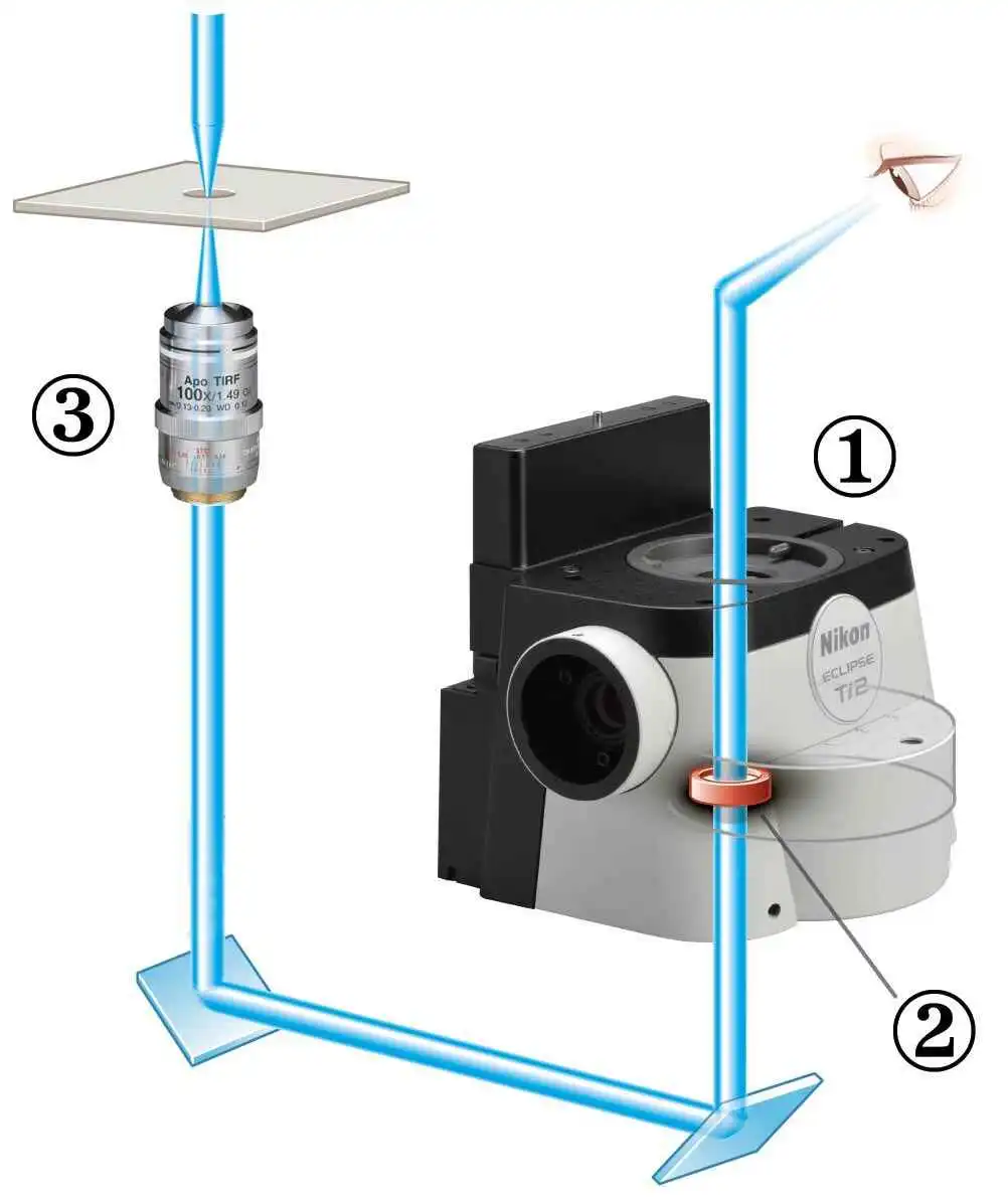
- Eyepiece base unit with built-in phase ring
- Phase ring
- Objective lens without phase ring
Epi-fluorescence and external phase contrast images:
PTK-1 cells labeled with GFP-alpha-tubulin captured with CFI Apochromat TIRF 100XC Oil objective.
Photo courtesy of Alexey Khodjakov, Ph.D Research Scientist VI / Professor, Wadsworth Center
DIC (Differential Interference Contrast)
Nikon's highly-regarded DIC optics provide uniformly clear and detailed images with high resolution and contrast throughout the magnification range. DIC prisms are individually tailored for each objective lens to provide the highest-quality DIC images for every sample.
成贯仪器)

DIC prisms matched to individual objectives are mounted in the nosepiece
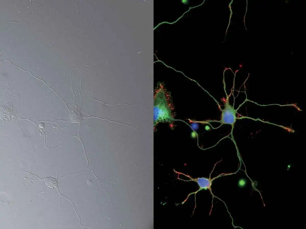
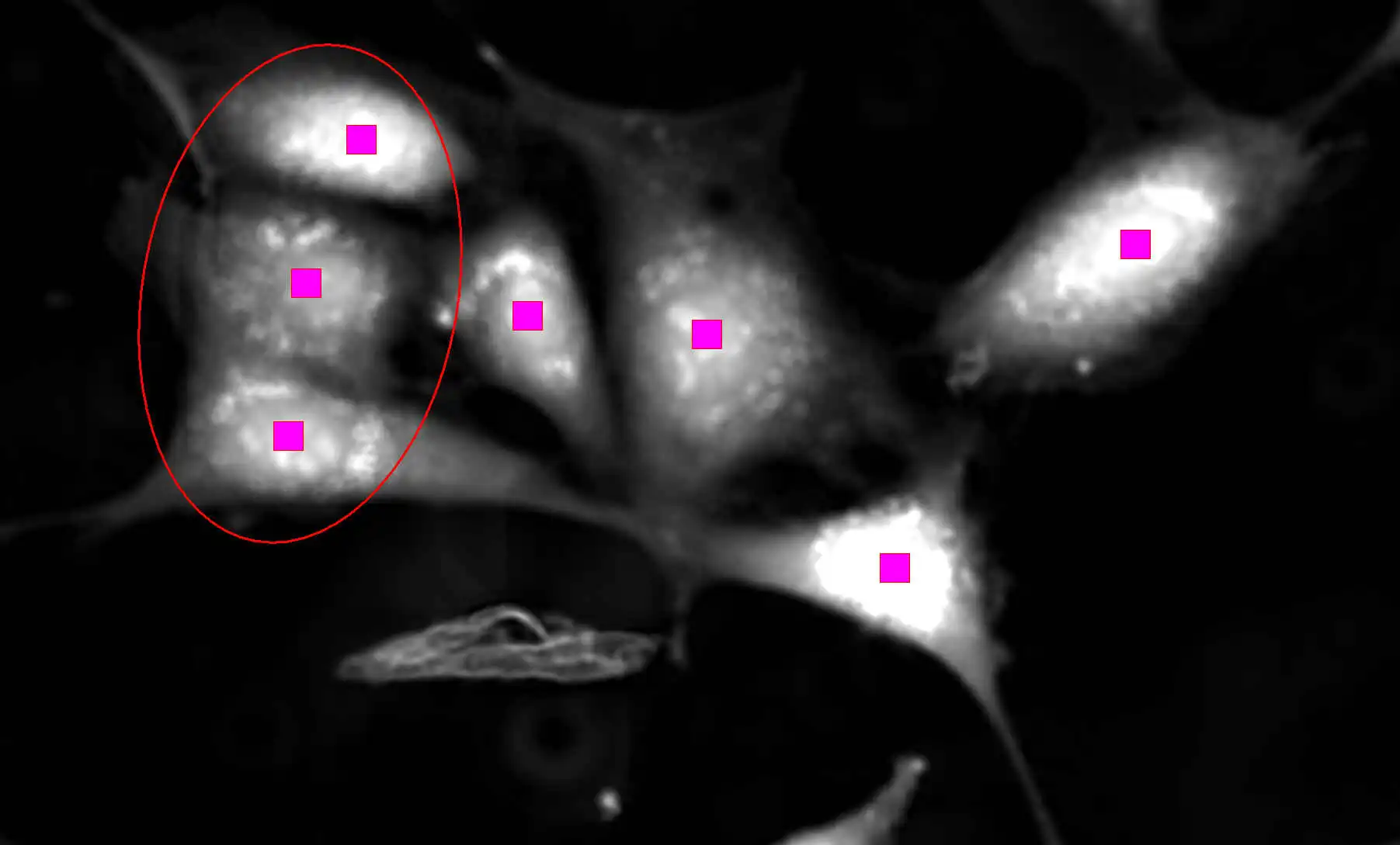
DIC and epi-fluorescence images:
25mm FOV image of neurons (DAPI, Alexa Fluor® 488, Rhodamine-Phalloidin), captured with CFI Plan Apochromat Lambda 60XC objective and DS-Qi2 camera
Photo courtesy of Josh Rappoport, Nikon Imaging Center, Northwestern Univ.;
Sample courtesy of S. Kemal, B. Wang, and R. Vassar, Northwestern Univ.
NAMC (Nikon Advanced Modulation Contrast)
This is a plastic-compatible, high-contrast imaging technique for unstained, transparent samples such as oocytes. NAMC provides pseudo-three-dimensional images with a shadow-cast appearance. The direction of contrast can be easily adjusted for each sample.


NAMC objective lenses contain rotatable modulators NAMC image:Mouse embryos, captured with CFI S Plan Fluor ELWD NAMC 20XC objective
Auto Correction Collar
Changes in sample thickness, cover glass thickness, refractive index distribution in the sample, and temperature can lead to spherical aberration and image deterioration. The highest quality objectives are often equipped with correction collars to compensate for these changes, and precise positioning of the collar is critical in achieving high resolution, high contrast images. This new auto correction collar utilizes a harmonic drive and automatic correction algorithm that enable users to easily achieve precise collar adjustment to achieve optimum objective performance every time.

Harmonic drive mechanism for high-precision control of correction collar movement
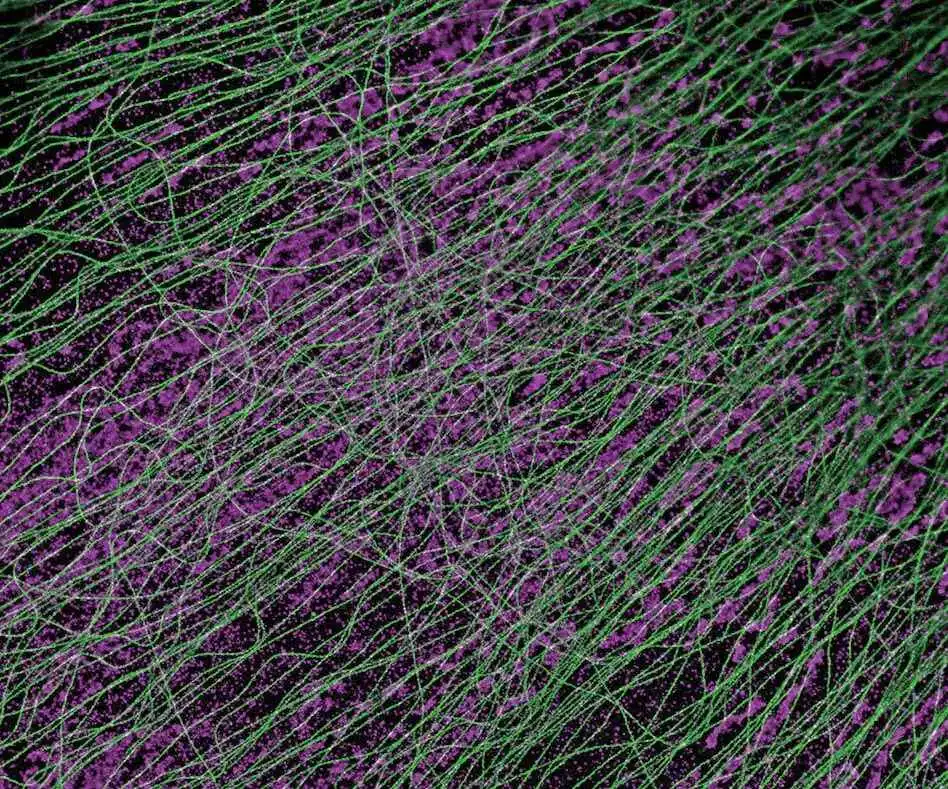
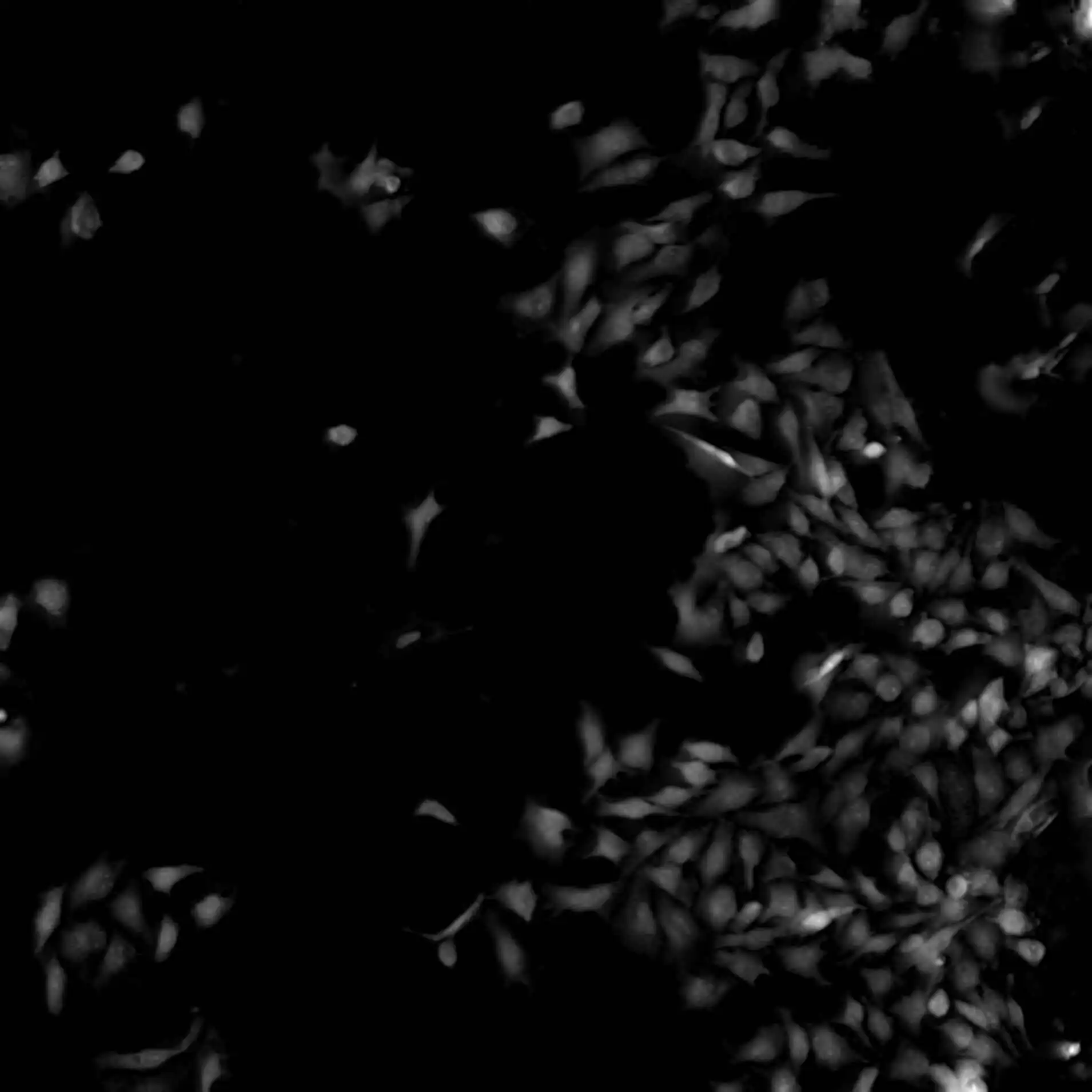
Super-resolution image (DNA PAINT):
CV-1 cells expressing α -tubulin (green) and TOMM-20 (magenta) captured with CFI Apochromat TIRF 100XC Oil objective.
Epi-fluorescence
The Lambda series objectives, utilizing Nikon's proprietary Nano Crystal Coat technology, are perfect for demanding, low-signal, multi-channel fluorescence imaging that requires high transmission and aberration correction over a wide wavelength range. Combined with new fluorescence filter cubes that offer improved fluorescence detection and stray light countermeasures such as the Noise Terminator, the Lambda series objectives demonstrate their power in weak signal observations such as single-molecule imaging and even luminescence-based applications.:成贯仪器)

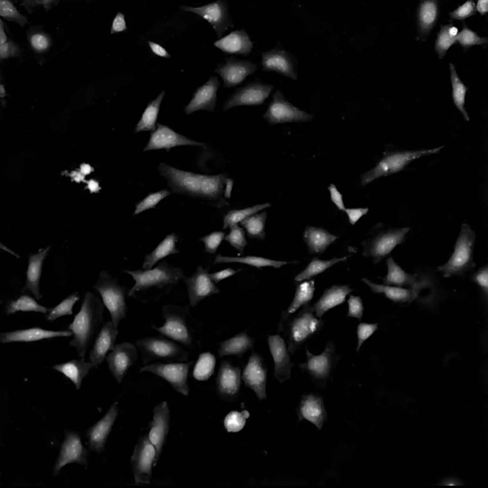
Luminescence image:
HeLa cells expressing BRET-based calcium indicator protein, Nano-lantern (Ca2+).
Sample courtesy of Prof. Takeharu Nagai, The Institute of Scientific and Industrial Research, Osaka University
Volume Contrast
Volume Contrast technique utilizes a series of label-free, brightfield images captured at various Z-depths to assemble a phase distribution image.
Volume Contrast renders cells easily identifiable as objects for automated counting and area analysis. As this method utilizes brightfield imaging, Volume Contrast enables in-line, non-destructive analysis of cells, suitable for a wide variety applications. Note. For Ti2-E only.

Brightfield Volume Contrast
HeLa cells imaged with CFI S Plan Fluor ELWD 20XC
Features of Volume Contrast(VC)
Accurate identification of cells from label-free cultures for automated cell counting and area measurements.

Cell identification based on phase contrast images Cell identification using VC images
Cells encircled in red are incorrectly identified as a single object. Cells encircled in red are correctly identified as three separate objects, resulting in accurate cell counts.
Negligible Meniscus Effect on Cell Identification
Phase contrast images are negatively impacted at the edges of wells due to the meniscus effect. Volume Contrast bypasses this effect and enables cells at the edges of wells to be clearly identified, resulting in increased cell counts and improved statistics.

Phase contrast image VC image
Mechanically redesigned for ultra-high stability
In order to improve the focusing stability, both Z-drive and PFS autofocusing mechanisms have been completely re-designed.
The new Z-focusing mechanism is smaller and positioned adjacent to the nosepiece to minimize vibrations. It remains adjacent to the nosepiece even in an expanded (staged-up) configuration, ensuring stability for all applications.
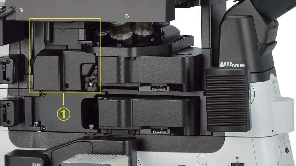
① High stability Z-focusing mechanism remains adjacent to the nosepiece even in expanded configurations
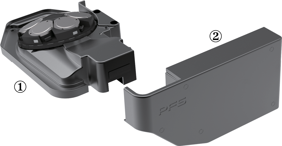
The detector portion of the Perfect Focus System (PFS) has been detached from the nosepiece in order to reduce mechanical load on the objective nosepiece. This new design also minimizes heat transfer, which contributes to a more stable imaging environment. Towards this end, the power consumption of the Z-drive motor has also been reduced. Combined, these mechanical redesigns result in an ultra-stable imaging platform, perfectly suited for single-molecule imaging and super-resolution applications.
High stability Z-focusing mechanism remains adjacent to the nosepiece even in expanded configurations.
① PFS nosepiece
② PFS Measuring Unit
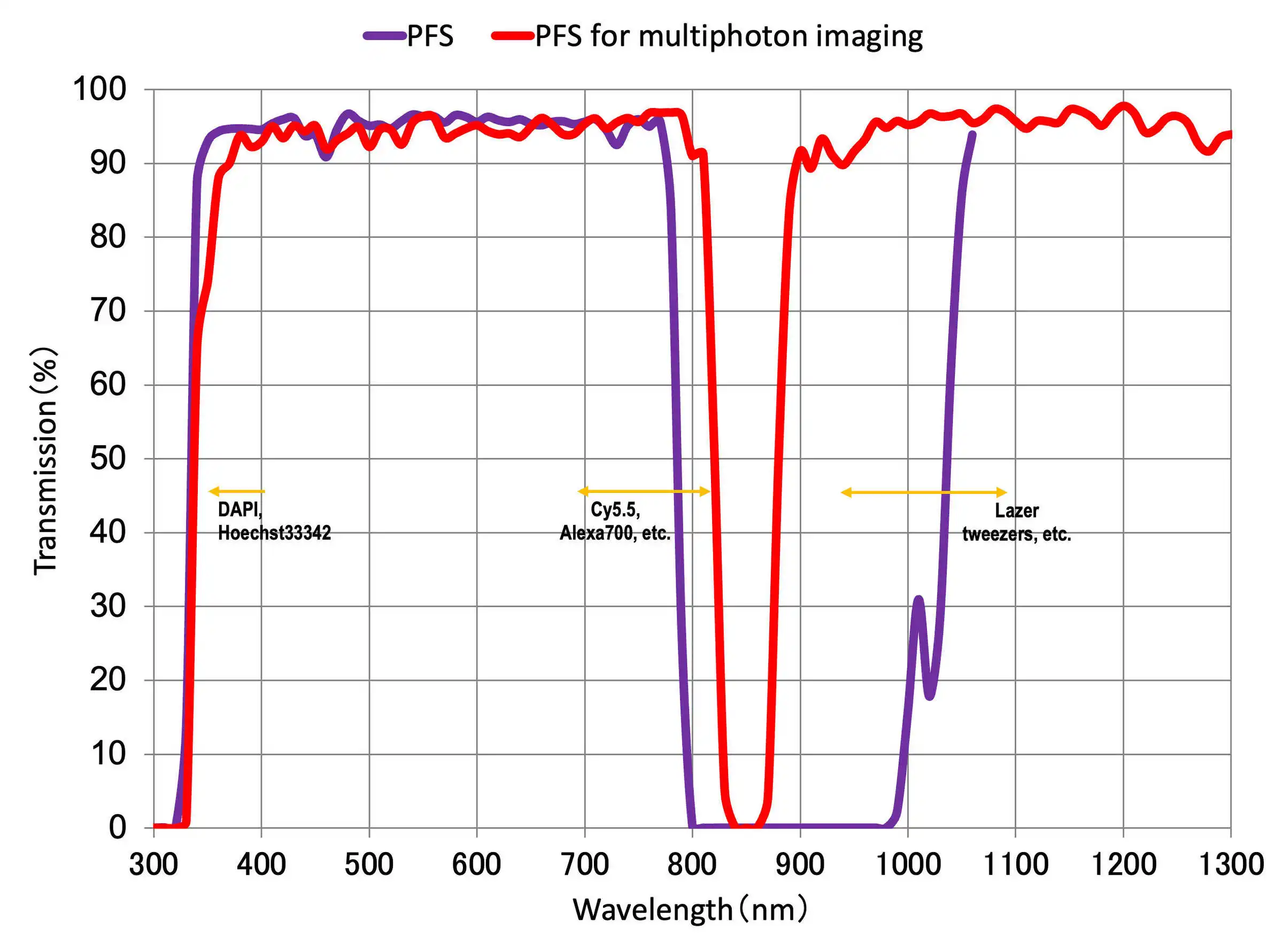
Real time focus correction with the PFS: Simply perfect
The Perfect Focus System (PFS) automatically corrects focus drift caused by temperature changes and mechanical vibrations, which can be caused by a variety of factors including the addition of reagents to the sample and multi-position imaging.
The PFS maintains focus by detecting and tracking the position of the coverslip surface in real time. Unique optical offset technology allows users to easily maintain focus at a desired position offset from the cover slip surface. The PFS automatically and continuously maintains focus by means of a built-in linear encoder and high speed feedback mechanism, providing highly reliable images even during long-term, complex imaging tasks.
PFS is compatible with a wide range of applications, from routine experiments involving plastic culture dishes to single-molecule imaging and multi-photon imaging. It is also compatible with a wide range of wavelengths, from ultraviolet to infrared, meaning it can be used for multi-photon and optical tweezer applications.

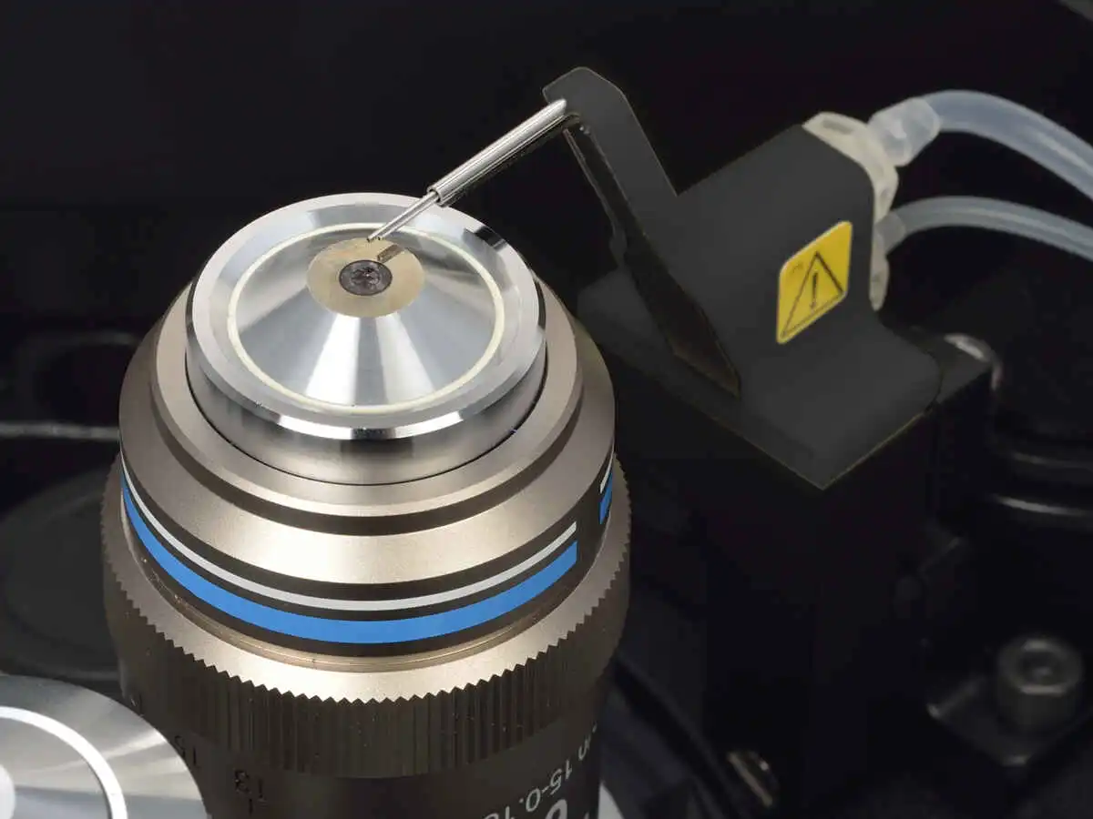
Water Immersion Dispenser
The performance of long-term imaging using the PFS together with water immersion objectives can be increased by using the new Water Immersion Dispenser. The Water Immersion Dispenser automatically applies the appropriate amount of pure water to the tip of an objective, preventing the immersion liquid from drying out and overflowing during experiments. It is compatible with all types of water immersion objectives and helps to stably provide high-resolution, high-contrast and aberration-corrected time-lapse images over long periods of time.

Compatible objectives
- CFI Apochromat LWD Lambda S 20XC WI
- CFI Apochromat Lambda S 40XC WI
- CFI Apochromat LWD Lambda S 40XC WI
- CFI Plan Apochromat VC 60XC WI
- CFI Plan Apochromat IR 60XC WI
- CFI SR Plan Apochromat IR 60XC WI
- CFI SR Plan Apochromat IR 60XAC WI
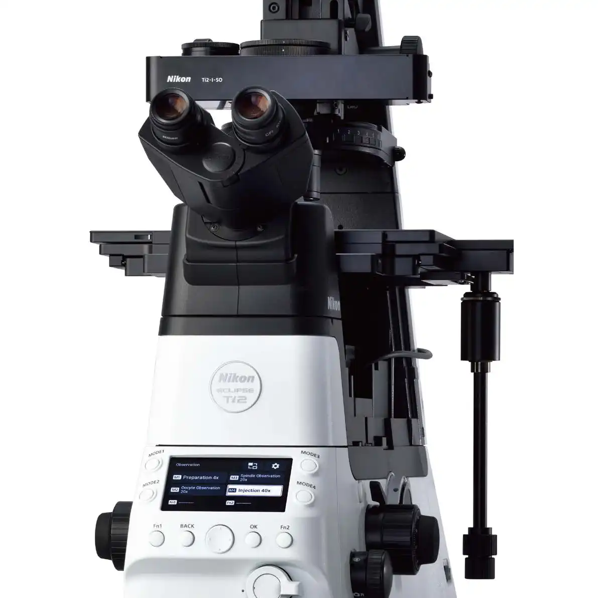
Assist Guide
It is no longer necessary to memorize complex microscope alignment and operation procedures. The Ti2 integrates data from sensors to guide you through these steps, eliminating user error and enabling researchers to concentrate on their data.
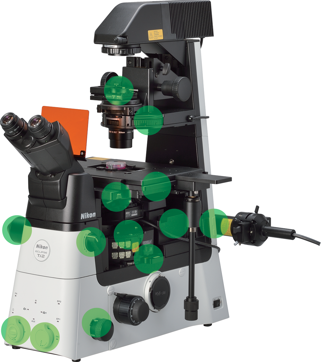
Built-in sensors detect the status of microscope components
Continuous display of microscope status
A collection of built-in sensors detects and relays status information for a variety of components in the microscope. All of the status information is recorded in the metadata when you acquire images with a computer, so you can easily recall acquisition conditions and/or check for configuration errors.
In addition, a built-in internal camera allows users to view the back aperture, facilitating confirmation of phase ring alignment and extinction cross in DIC. It also provides a laser-safe method for aligning lasers for applications such as TIRF.
Microscope status can be viewed on a tablet and also determined based on status lights on the front of the microscope, enabling status determination in a dark room.
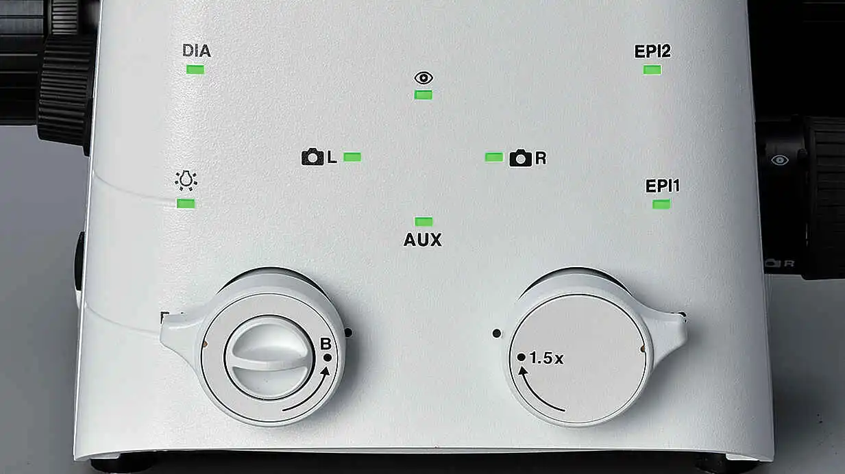
Status Lights
Guidance for operational procedures
The Ti2's Assist Guide function provides interactive step-by-step guidance for microscope operation. The Assist Guide can be viewed on a tablet or PC, and integrates real time data from built-in sensors and an internal camera. The Assist Guide is designed to help users through alignment procedures for both experiment setup and troubleshooting.
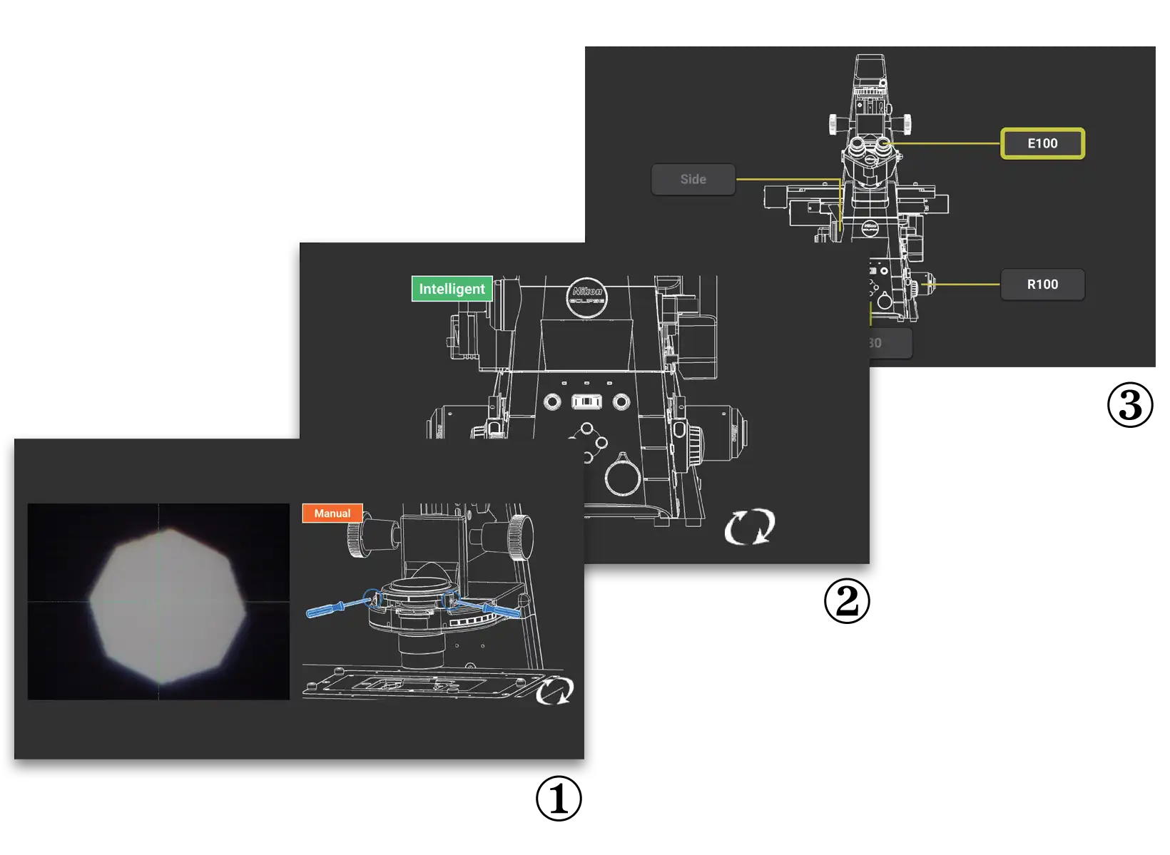
① Move the field diaphragm image to the center of the field view
② Remove the Bertrand lens from the optical path
③ Select an observation port
Automatically detect errors
The Check Mode allows users to easily confirm, on either a tablet or PC that all the correct microscope components are in place for their chosen observation method. This capability eliminates time and effort normally required for troubleshooting when the desired observation method is not achieved. This functionality is particularly advantageous when multiple users are involved, each with the potential to make unexpected changes to the microscope settings. Custom check procedures can also be pre-programmed.
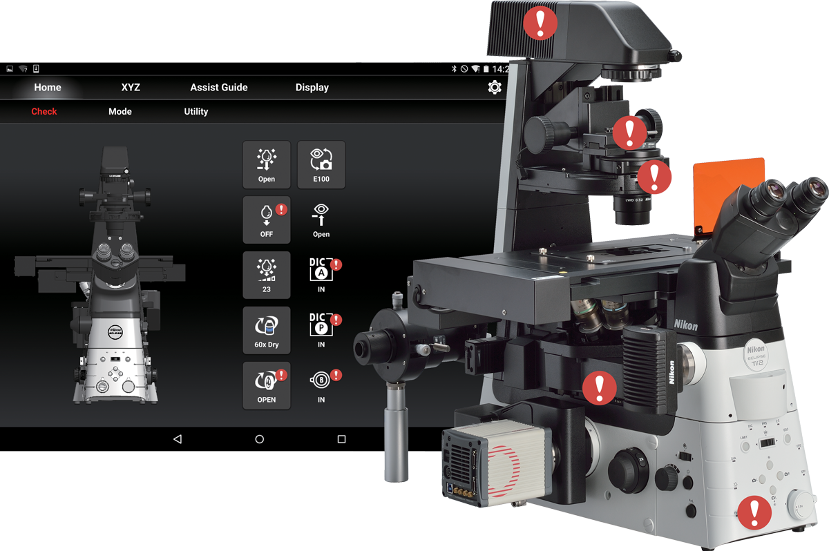
Displays misaligned components
Intuitive operation
The Ti2 has been completely redesigned, from the overall body design to the selection and placement of every button and switch, for the ultimate in user experience. The controls are easy to use even in the dark, where the majority of imaging experiments are conducted. The Ti2 provides an intuitive and effortless user interface so researchers can focus on the data and not on microscope control.
Thoughtfully designed layout for microscope control
The placement of all of the buttons and switches are based on the type of illumination they control. Buttons that control diascopicobservation are positioned on the left side of the microscope and those that control epi-fluorescence observation are on the right side. Buttons that control common operations are on the front panel. This use of zoning provides an easy-to-remember layout, a desirable feature when operating the microscope in a dark room.
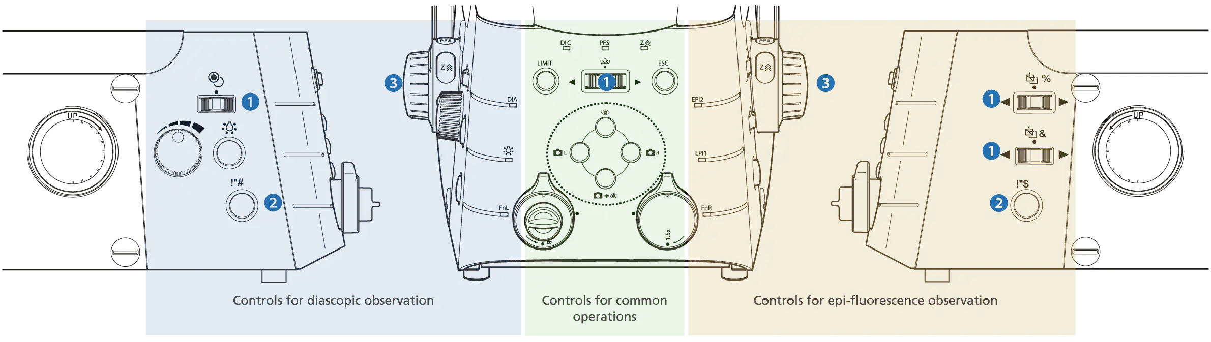
① Shuttle switch (Ti2-E)
Shuttle switches have been incorporated into the design to control devices such as the fluorescence filter turret and objective nosepiece. These types of switches emulate the feel of manually rotating these devices, for intuitive control. Additional functionality can be incorporated into these shuttle switches so that a single switch can operate multiple related devices. For example, the shuttle switch for the fluorescence filter turret not only rotates the turret but also opens and closes the fluorescence shutter when the user presses the switch. It is also possible to program these switches to operate a barrier filter wheel and the external phase contrast unit.
② Programmable Function button (Ti2-E/A)
Conveniently located Function buttons allow customization of the user interface. Users can select from more than 100 functions, including control of motorized devices such as shutters and even signal output to external devices via the I/O port for triggered acquisition. Mode functions, which enable instant changing of observation methods by storing the settings of each motorized device, can also be assigned to these buttons.
③ Focusing knob (Ti2-E)
A focus acceleration button and a PFS engagement button are provided adjacent to the focusing knobs. The two buttons are easily identified by touch because of their different shapes. Focusing speed is automatically adjusted for the objective in use, enabling stress-free operation by maintaining an ideal focusing speed.
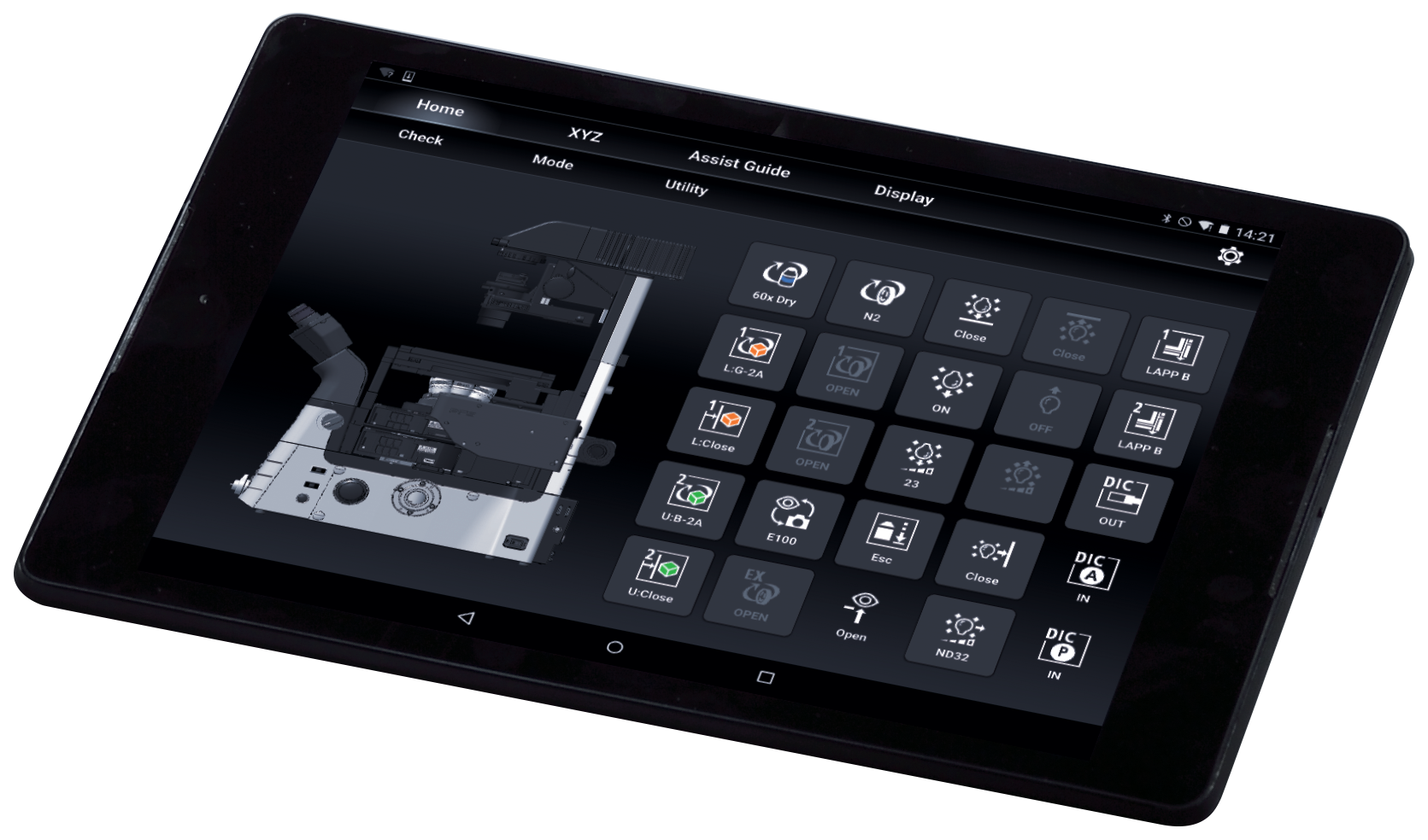
Intuitive control with joystick and tablet
The Ti2 joystick not only controls stage movement, but the majority of motorized functions on the microscope, including PFS activity. It can display XYZ coordinates and the status of microscope components, providing an effective means for the user to remotely control the microscope. Motorized functions of the Ti2 can also be controlled from a tablet, connected by wireless LAN to the microscope, providing a versatile graphical interface for microscope control.


 Microsystem
 Endoscopysystem
 Energysystem
 EndoscopyConsumables
 +86-21-54286005
 Room 602, Building 1, No. 111 Luxiang Road (Greenland Park Plaza), Baoshan District, Shanghai, China
  English
 中文
中文
 ECLIPSE Ti2_Brochure_EN


 中文
中文 English