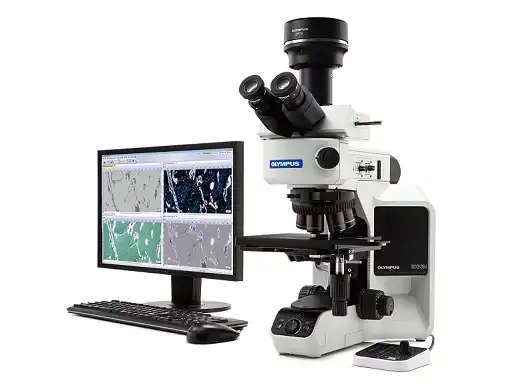
Advanced Microscopy Simplified
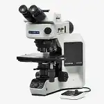
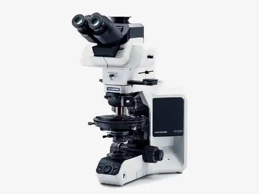
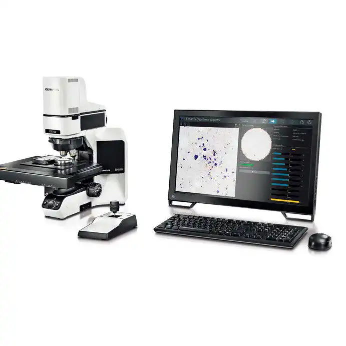
Designed with modularity in mind, the BX3M series provide versatility for a wide variety of materials science and industrial applications. With improved integration with PRECiV software, the BX53M provides a seamless workflow for standard microscopy and digital imaging users from observation to report creation.
Choose the Best Model
Six BX53M suggested configuration provide you with flexibility to choose the features that you need.
- For General use: Entry, Standard, Advanced
- For Dedicated use: Fluorescence, Infrared, Polarization
- Various configurations to meet users' requirements
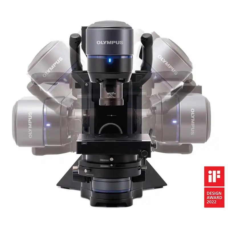
- Modular Design, Build Your System Your Way
Comfortable and Easy to Use
The BX53M simplifies complex microscopy tasks through its well-designed and easy-to-use controls. Users can get the most out of the microscope without the need for extensive training. The easy, comfortable operation of the BX53M also improves reproducibility by minimizing human error.
- Simple Illuminator
- Intuitive Microscope Controls
- Find the Focus Quickly
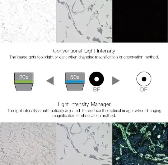
- Consistent Illumination
- Easy and Ergonomic Operation
- Easy Restore Microscope Settings
- Basic Measurement Functions
Functional
The BX53M maintains the traditional contrast methods of conventional microscopy, such as brightfield, darkfield, polarized light, and differential interference contrast. As new materials are developed, many of the difficulties associated with detecting defects using standard contrast methods can be solved using advanced microscopy techniques for more accurate and reliable inspections. New illumination techniques and options for image acquisition within PRECiV image analysis software give users more choices of how to evaluate their samples and document findings.
- The Invisible Becomes Visible
- Create All-in-focus Images
- Easily Move the Stage for Panorama
- Capture Both Bright and Dark Areas
- Adaptable to Suit Observational and Analysis Preferences
- Accommodates a Wide Range of Samples
Leading-Edge Optics
Olympus’ history of developing high-quality optics has resulted in a record of proven optical quality and microscopes that offer excellent measurement accuracy.
- Superior Optical Performance
- Stable Color Temperature and High-Intensity White LED Illumination
- Support Precise Measurement
- Seamless Stitching
Wave Front Aberration Control
|
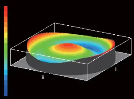
Bad wavefront
|
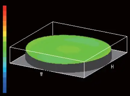
Good wavefront (UIS2 objective)
|
Highly Reliable Modular System Concept
Never in This Simplicity
| General Use |
Dedicated Use |
|
|
|
Entry
Easy setup with basic features
|
Standard
Simple to use with versatile upgrades
|
Advanced
Supports numerous advanced features
|
Fluorescence
Ideally suited for Fluorescence observation
|
Infrared
Designed to use Infrared observation to inspect integrated circuits
|
Polarization
Designed for observing birefringence characteristics
|
|

LCD color filter (Transmitted/BF)
|
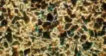
Microstructure with ferritic grains
(Reflected/DF)
|
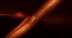
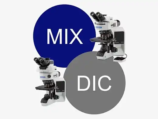
Copper wire of coil
(BF + DF/MIX)
|
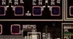
Resist on IC pattern
(FL + DF/MIX)
|
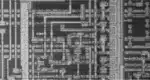
Silicon layering IC pattern
(IR)
|
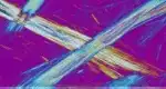
Asbestos
(POL)
|
|
|
|
|
|
|
|
OBSERVATION METHOD
R-BF: Brightfield (Reflected)
T-BF: Brightfield (Reflected/Transmitted)
DF: Darkfield
DIC: Differential interference contrast / Simple polarization
MIX: MIX
FL: Fluorescence
IR: Infrared
POL: Polarization
*T-BF can be used when selecting Reflected/Transmitted microscope frame.
 : Standard
 : Option
Example Configurations for Materials Science
Modular design enables various configurations to meet users’ requirements.
Below you can find some examples of configuration for materials science.
BX53M Reflected and Reflected/Transmitted Light Combination
There are two types of microscope frames in the BX3M series, one for reflected light only and one for both reflected and transmitted light. Both frames can be configured with manual, coded, or motorized components. The frames are outfitted with ESD capability to protect electronic samples.
|
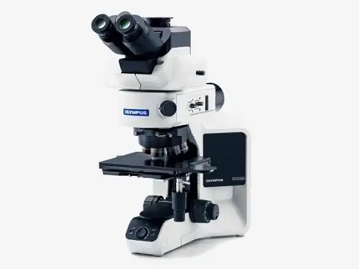
BX53MRF-S example configuration
|
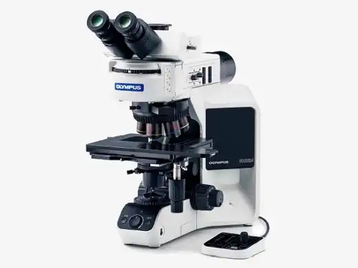
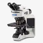
BX53MTRF-S example configuration
|
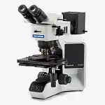
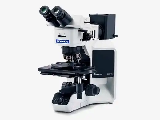
BX53M IR Combination
IR objectives can be used for semiconductor inspection, measurement, and processing applications where imaging through silicon is required to see the pattern. 5X to 100X infrared (IR) objectives are available with chromatic aberration correction from visible light wavelengths through the near infrared. For high magnification work, rotating the correction collar of the LCPLNIR series of lenses corrects for aberrations caused by sample thickness. A clear image is obtained with a single objective.
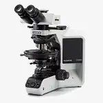
BX53M Polarized Light Combination
The optics of the BX53M polarized light provide geologists with the right tools for high-contrast polarized light imaging. Applications such as mineral identification, investigating the optical characteristics of crystals, and observing solid rock sections benefit from system stability and precise optical alignment.
|
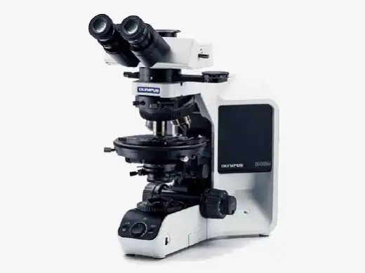
BX53-P orthoscopic configuration
|
BX53-P conoscopic/orthoscopic configuration
|
Bertrand Lens for Conoscopic and Orthoscopic Observations
With a U-CPA conoscopic observation attachment, switching between orthoscopic and conoscopic observation is simple and fast. It is focusable for clear back focal plane interference patterns. The Bertrand field stop makes it possible to obtain consistently sharp and clear conoscopic images.
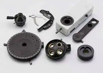
An Extensive Range of Compensator and Wave Plates
Six different compensators are available for measurements of birefringence in rock and mineral thin sections. Measurement retardation level ranges from 0 to 20λ. For easier measurement and high image contrast, the Berek and Senarmont compensators can be used, which change the retardation level in the entire field of view.
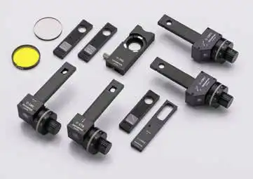
Measuring Range of Compensators
| Compensator |
Measuring Range |
Major Application |
| Thick Berek (U-CTB) |
0 to 11,000 nm
(20 λ) |
Measurement of High Retardation Level (R*>3λ)
(crystals, macromolecules, fiber, etc.) |
| Berek (U-CBE) |
0 to 1,640 nm
(3 λ) |
Measurement of Retardation Level
(crystals, macromolecules, living organisms, etc.) |
| Senarmont Compensator (U-CSE) |
0 to 546 nm
(1 λ) |
Measurement of Retardation Level (crystals, living organisms, etc.)
Enhancement of Image Contrast (living organisms, etc.) |
Brace-Koehler Compensator
1/10λ (U-CBR1) |
0 to 55 nm
(1/10 λ) |
Measurement of Low Retardation Level (living organisms, etc.)
Enhancement of Image Contrast (living organisms, etc.) |
Brace-Koehler Compensator
1/30λ (U-CBE2) |
0 to 20 nm
(1/30 λ) |
Measurement of image contrast (living organisms, etc.) |
| Quartz Wedge (U-CWE2) |
500 to 2,200 nm
(4 λ) |
Approximate Measurement of Retardation Level
(crystal, macromolecules, etc.) |
*R = retardation level
For more accurate measurement, it is recommended that compensators (except U-CWE2) be used together with the interference filter 45-IF546.
Strain Free Optics
Thanks to Olympus’ sophisticated design and manufacturing technology, the UPLFLN-P strainfree objectives reduce internal strain to the minimum. This means a higher EF value, resulting in excellent image contrast.
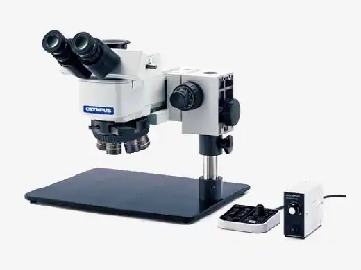
BXFM System
The BXFM can be adapted to special applications or integrated into other instruments. The modular construction provides for straightforward adaptation to unique environments and configurations with a variety of special small illuminators and fixturing mounts.
Modular Design, Build Your System Your Way
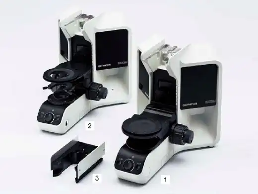
Microscope Frames
There are two microscope frames for reflected light, one also has transmitted Light; capability. An adapter is available to raise the illuminator to accommodate taller samples.
|
|
|
Reflected light |
Transmitted light |
Sample height |
| 1 |
BX53MRF-S |
■ |
- |
0 to 65 mm |
| 2 |
BX53MTRF-S |
■ |
■ |
0 to 35 mm |
| 1, 3 |
BX53MRF-S + BX3M-ARMAD |
■ |
- |
40 to 105 mm |
| 2, 3 |
BX53MTRF-S + BX3M-ARMAD |
■ |
■ |
40 to 75 mm |
Convenient Accessories for Microscopy use
| - |
HP-2 |
Hand press |
| - |
COVER-018 |
Dust cover |
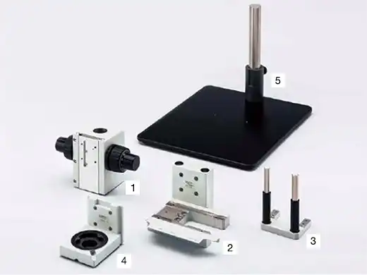
Stands
For microscopy applications where the sample will not fit on a stage, the illuminator and optics can be mounted to a larger stand or to another piece of equipment.
BXFM + BX53M Illuminator Configuration
| 1 |
BXFM-F |
Frame interface is wall mounting 32 mm pillar |
| 2 |
BX3M-ILH |
Illuminator holder |
| 3 |
BXFM-ILHSPU |
Counter spring for BXFM |
| 5 |
SZ-STL |
Large stand |
BXFM + U-KMAS Illuminator Configuration
| 1 |
BXFM-F |
Frame interface is wall mounting 32 mm pillar |
| 4 |
BXFM-ILHS |
U-KMAS holder |
| 5 |
SZ-STL |
Large stand |
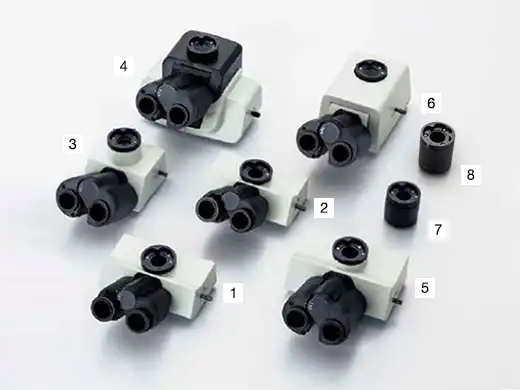
Tubes
For microscope imaging with eyepieces or for camera observation, select tubes by imaging type and operator’s posture during observation.
|
|
|
FN |
Type |
Angle type |
Image |
Number of diopter
adjustment mechanisms |
| 1 |
U-TR30-2 |
22 |
Trinocular |
Fixing |
Reverse |
1 |
| 2 |
U-TR30IR |
22 |
Trinocular for IR |
Fixing |
Reverse |
1 |
| 3 |
U-ETR-4 |
22 |
Trinocular |
Fixing |
Erect |
- |
| 4 |
U-TTR-2 |
22 |
Trinocular |
Tilting |
Reverse |
- |
| 5 |
U-SWTR-3 |
26.5 |
Trinocular |
Fixing |
Reverse |
- |
| 6 |
U-SWETTR-5 |
26.5 |
Trinocular |
Tilting |
Erect |
- |
| 7 |
U-TLU |
22 |
Single port |
- |
- |
- |
| 8 |
U-SWATLU |
26.5 |
Single port |
- |
- |
- |
Illuminators
The illuminator projects light onto the sample based on the observation method selected. Software interfaces with coded illuminators to read the cube position and automatically recognize the observation method.
| Coded function |
Light source |
BF |
DF |
DIC |
POL |
IR |
FL |
MIX |
AS/FS |
| 1 |
BX3M-RLAS-S |
Fixed 3 cube position |
LED - Built in |
■ |
■ |
■ |
■ |
- |
- |
■ |
■ |
| 2 |
BX3M-URAS-S |
Attachable 4 cube position |
LED |
■ |
■ |
■ |
■ |
- |
- |
■ |
■ |
| Halogen |
■ |
■ |
■ |
■ |
■ |
- |
■ |
■ |
| Mercury/Light guide |
■ |
■ |
■ |
■ |
- |
■ |
■ |
■ |
| 3 |
BX3M-RLA-S |
|
LED |
■ |
■ |
■ |
■ |
- |
- |
■ |
■ |
| Halogen |
■ |
■ |
■ |
■ |
■ |
- |
■ |
■ |
| 4 |
SPECIFICATIONS OF BX53M SUGGESTED CONFIGURATION FOR GENERAL USE
|
|
Entry |
Standard |
Advanced |
| Optical system |
UIS2 optical system (infinity-corrected) |
| Main unit |
Microscope frame |
BX53MRF-S
(Reflected) |
BX53MTRF-S
(Reflected/Transmitted) |
BX53MRF-S
(Reflected) |
BX53MTRF-S
(Reflected/Transmitted) |
BX53MRF-S
(Reflected) |
BX53MTRF-S
(Reflected/Transmitted) |
| Focus |
Stroke: 25 mm
Fine stroke per rotation: 100 μm
Minimum graduation: 1 μm
With upper limit stopper, torque adjustment for coarse handle |
| Max. specimen height |
Reflected: 65 mm (w/o spacer), 105 mm (with BX3M-ARMAD)
Reflected/Transmitted: 35 mm (w/o spacer), 75 mm (with BX3M-ARMAD) |
| Observation tube |
Wide field (F.N.22) |
U-TR30-2-2
Inverted: trinocular |
| Illumination |
Reflected light
Transmitted light |
BX3M-KMA-S
White LED, BF/DIC/POL/MIX FS,
AS (with centering mechanism), BF/DF interlocking |
BX3M-RLAS-S
Coded, White LED, BF/DF/DIC/POL/MIX FS,
AS (with centering mechanism), BF/DF interlocking |
| - |
BX3M-LEDT
White LED
Abbe/long working distance condensers |
- |
BX3M-LEDT
White LED
Abbe/long working distance condensers |
- |
BX3M-LEDT
White LED
Abbe/long working distance condensers |
| Revolving nosepiece |
U-5RE-2
For BF: Quintuple |
U-D6BDRE
For BF/DF: Sextuple |
U-D6BDRES-S
For BF/DF : Sextuple, Coded |
| Eyepiece(F.N.22) |
WHN10
WHN10X-H |
| MIX observation |
- |
BX3M-CB
Control box
BX3M-HS
Hand switch
U-MIXR-2
MIX slider for reflected light observation
U-MIXRCBL
Cable for MIXR |
| Condenser (Long working distance) |
- |
U-LWCD |
- |
U-LWCD |
- |
U-LWCD |
| Power cable |
UYCP (x1) |
UYCP (x2) |
| Weight |
Reflected: approx.15.8 kg (microscope frame 7.4 kg)
Reflected/transmitted: approx. 18.3 kg (microscope frame 7.6 kg) |
| Objectives |
MPLFLN set |
MPLFLN5X, 10X, 20X, 50X, 100X
BF/POL/FL observation |
- |
| MPLFLN BD set |
- |
MPLFLN5XBD, 10XBD, BD, 50XBD, 100XBD
BF/DF/DIC/POL/FL observation |
| MPLFLN-BD, LMPLFLN-BD set |
- |
MPLFLN5XBD, 10XBD,
MPLFLN20XBD, 50XBD, 100XBD
BF/DF/DIC/POL/FL observation |
| MPLFLN-BD, MXPLFLN-BD, LMPLFLN-BD set |
- |
MPLFLN5XBD, 10XBD,
MXPLFLN20XBD, 50XBD,
LMPLFLN20XBD, 50XBD, 100XBD
BF/DF/DIC/POL/FL observation |
| Stage (X x Y) |
76 mm x 52 mm set |
U-SVRM, U-MSSP
Coaxial right handle stage / 76 (X) × 52 (Y) mm, with torque adjustment |
| 100 mm x 10 0mm set |
U-SIC4R2, U-MSSP4
Large-size coaxial right handle stage / 100 (X) x 100 (Y) mm, with lock mechanism in Y axis |
| 100 mm x 100 (G) mm set |
U-SIC4R2, U-MSSPG
Large-size coaxial right handle stage / 100 (X) x 100 (Y) mm, with lock mechanism in Y axis (Glass plate) |
| 150 mm x 100 mm set |
U-SIC64, U-SHG, U-SP64
Large-size coaxial right handle stage / 150 (X) x 100 (Y) mm, with torque adjustment, with lock mechanism in Y axis |
| 150 mm x 100 (G) mm set |
U-SIC64, U-SHG, U-SPG64
Large-size coaxial right handle stage / 150 (X) x 100 (Y) mm, with torque adjustment, with lock mechanism in Y axis (Glass plate) |
| Option |
MIX observation set* |
BX3M-CB, BX3M-HS, U-MIXR-2, U-MIXRCBL |
- |
| DIC* |
U-DICR |
| Intermediate Tubes |
U-CA, U-EPA2, U-TRU |
| Filters |
U-25ND6, U-25ND25, U-25LBD, U-25LBA, U-25Y48, U-AN360-3,
U-AN360P, U-PO3, U-POTP3, U-25IF550, U-25L42, U-25, U-25FR
|
| Filter for condenser |
43IF550-W45, U-POT |
| Stage plate |
U-WHP64, BH2-WHR43, BH2-WHR54, BH2-WHR65, U-WHP2 |
| Specimen holder |
U-HRD-4, U-HLD-4, U-HRDT-4, U-HLDT-4 |
| Handle rubber |
U-SHG, U-SHGT |
*Cannot be used with U-5RE-2.
BX53M / BXFM ESD UNITS
| Items |
Microscope frame |
BX53MRF-S, BX53MTRF-S |
| Illuminator |
BX3M-KMA-S, BX3M-RLA-S, BX3M-URAS-S, BX3M-RLAS-S |
| Nosepiece |
U-D6BDREMC, U-D6BDRES-S, U-D6RE-ESD, U-D5BDREMC-ESD, U-5RES-ESD |
| Stage |
U-SIC4R2, U-MSSP4 |
SPECIFICATIONS OF BX53M SUGGESTED CONFIGURATION FOR DEDICATED USE
| Fluorescence |
Infrared |
Polarized |
| Optical system |
UIS2 optical system (infinity-corrected) |
| Main unit |
Microscope frame |
BX53MRF-S
(Reflected) |
BX53MTRF-S
(Reflected/ Transmitted) |
BX53MRF-S
(Reflected) |
BX53MTRF-S
(Reflected/Transmitted) |
| Focus |
Stroke: 25 mm
Fine stroke per rotation: 100 μm
Minimum graduation: 1 μm
With upper limit stopper, torque adjustment for coarse handle |
| Max. specimen height |
Reflected: 65 mm (w/o spacer), 105 mm (with BX3M-ARMAD)
Reflected/Transmitted: 35 mm (w/o spacer), 75 mm (with BX3M-ARMAD) |
| Observation tube |
Wide field (F.N.22) |
U-TR30-2
Inverted: trinocular |
U-TR30IR
Inverted: trinocular for IR |
U-TR30-2
Inverted: trinocular |
| Polarized Light Intermediate Attachment (U-CPA) |
Bertrand Lens |
- |
- |
Focusable |
| Bertrand Field Stop |
- |
- |
ø3.4 mm diameter (fixed) |
| Engage or disengage Bertrand lens changeover between orthoscopic and conoscopic observation |
- |
- |
Position of slider ● in
Position of slider ○ out |
| Analyzer Slot |
- |
- |
Rotatable Analyzer with Slot (U-AN360P-2) |
| Illumination |
Reflected light |
FL observation |
BX3M-URAS-S
Coded universal reflected light, 4 position mirror unit turret, (standard: U-FWUS, U-FWBS, U-FWGS, U-FBF etc) With FS, AS (with centering mechanism), With shutter mechanism |
- |
- |
| IR observation |
- |
BX3M-RLA-S
100W halogen lamp for IR, BF/IR, AS (with centering mechanism)
U-LH100IR (Including 12V 10W HAL-L)
100W Halogen light source for IR
TH4-100
100W power supply
TH4-HS
Hand switch
U-RMT
Extension cord |
- |
| Transmitted light |
POL observation |
- |
- |
BX3M-LEDT
White LED
Abbe/long working distance condensers |
| Revolving nosepiece |
U-D6BDRES-S
For BF/DF : Sextuple, Coded |
U-5RE-2
For BF : Quintuple |
U-P4RE
Quadruple, centerable attachable components
1/4 wavelength retardation plate (U-TAD),
tint plate (U-TP530) and various compensators can
be attached using plate adapter (U-TAD) |
| Eyepiece(F.N.22) |
WHN10X |
| WHN10X-H |
CROSS-WHN10X |
| Mirror units |
U-FDF
For DF
U-FBFL
For BF, built-in ND filter
U-FBF
For BF, detactable ND filter
U-FWUS
For Ultra Violet-FL
U-FWBS
For Blue-FL
U-FWGS
For Green-FL |
- |
| Filter / Polarizer / Analyzer |
U-25FR
Frost filter |
U-BP1100IR/U-BP1200IR
Band path filters for IR |
43IF550-W45
Green filter |
U-POIR
Reflected polarizer slider for IR |
U-AN360IR
Rotatable analyzer slider for IR |
U-AN360P-2
360° Dial-rotatable
Rotatable minimum angle 0.1° |
| Condenser |
U-LWCD
Long working distance |
- |
U-POC-2
Achromat strain-free condenser.
360°rotatable polarizer
with swing-out achromatic top-lens.
Click stop at position "0°" is adjustable.
NA 0.9 (top-lens in)
/ NA 0.18 (top-lens out)
Aperture iris diaphragm:
adjustable from 2 mm to 21 mm diameters |
| Slider / Compensators |
- |
U-TAD
Slider (Plate adapter) |
U-TP530
Tint plate
U-TP137
1/4 wavelength retardation plate |
| Power cable |
UYCP (x1) |
UYCP (x2) |
UYCP (x1) |
| Weight |
Reflected: approx.15.8 kg (microscope frame 7.4 kg) |
Reflected/transmitted: approx. 18.3 kg (microscope frame 7.6 kg) |
Approx.18.9 kg (microscope frame 7.4 kg) |
Approx.16.2 kg (microscope frame 7.6 kg) |
| Reflected FL light source |
Light guide |
U-LGPS, U-LLGAD, U-LLG150, Light guide set |
- |
- |
| Mercury lamp |
U-LH100HGAPO1-7,
USH-103OL (x2), U-RFL-T,
U-RCV Mercury lamp set
|
- |
- |
| Objectives |
MPLFLN set |
MPLFLN5X, 10X, 20X, 50X, 100X
BF/DIC/POL/FL observation |
- |
- |
| MPLFLN BD set |
MPLFLN5XBD, 10XBD, BD, 50XBD, 100XBD
BF/DF/DIC/POL/FL observation |
- |
- |
| MPLFLN-BD, LMPLFLN-BD set |
MPLFLN5XBD, 10XBD,
LMPLFLN20XBD, 50XBD, 100XBD
BF/DF/DIC/POL/FL observation |
- |
- |
| MPLFLN-BD, MXPLFLN-BD, LMPLFLN-BD set |
MPLFLN5XBD, 10XBD,
MXPLFLN20XBD, 50XBD,
MPLFLN20XBD, 50XBD, 100XBD
BF/DF/DIC/POL/FL observation |
- |
- |
| IR set |
- |
LMPLN5XIR,10XIR,
LCPLN20XIR,50XIR,100XIR
IR observation |
- |
| POL set |
- |
- |
UPLFLN4XP,10XP,20XP,40XP
POL observation |
| Stage (X x Y) |
76 mm x 52 mm set |
U-SVRM, U-MSSP
Coaxial right handle stage / 76 (X) × 52 (Y) mm,
with torque adjustment |
| 100 mm x 10 0mm set |
U-SIC4R2, U-MSSP4
Large-size coaxial right handle stage / 100 (X) x 100 (Y) mm,
with lock mechanism in Y axis |
| 100 mm x 100 (G) mm set |
U-SIC4R2, U-MSSPG
Large-size coaxial right handle stage / 150 (X) x 100 (Y) mm,
with lock mechanism in Y axis (Glass plate) |
| 150 mm x 100 mm set |
U-SIC64, U-SHG, U-SP64
Large-size coaxial right handle stage / 150 (X) x 100 (Y) mm,
with torque adjustment, with lock mechanism in Y axis |
| 150 mm x 100 (G) mm set |
U-SIC64, U-SHG, U-SPG64
Large-size coaxial right handle stage / 150 (X) x 100 (Y) mm,
with torque adjustment, with lock mechanism in Y axis (Glass plate) |
| POL set |
- |
U-SRP+U-FMP
Polarizing rotatable stage + Mechanical stage |
| Option |
MIX observation set* |
BX3M-CB, BX3M-HS, U-MIXR-2, U-MIXRCBL |
| DIC* |
U-DICR |
| Intermediate Tubes |
U-CA, U-EPA2, U-TRU |
| Filters |
U-25ND6, U-25ND25, U-25LBD, U-25LBA, U-25Y48,
U-AN360-3, U-AN360P, U-PO3, U-POTP3, U-25IF550, U-25L42, U-25, U-25FR |
| Filter for condenser |
43IF550-W45, U-POT |
| Stage plate |
U-WHP64, BH2-WHR43, BH2-WHR54, BH2-WHR65, U-WHP2 |
| Specimen holder |
U-HRD-4, U-HLD-4, U-HRDT-4, U-HLDT-4 |
| Handle rubber |
U-SHG, U-SHGT |
*Cannot be used with U-5RE-2


 Microsystem
 Endoscopysystem
 Energysystem
 EndoscopyConsumables
 +86-21-54286005
 Room 602, Building 1, No. 111 Luxiang Road (Greenland Park Plaza), Baoshan District, Shanghai, China
  English
 中文
中文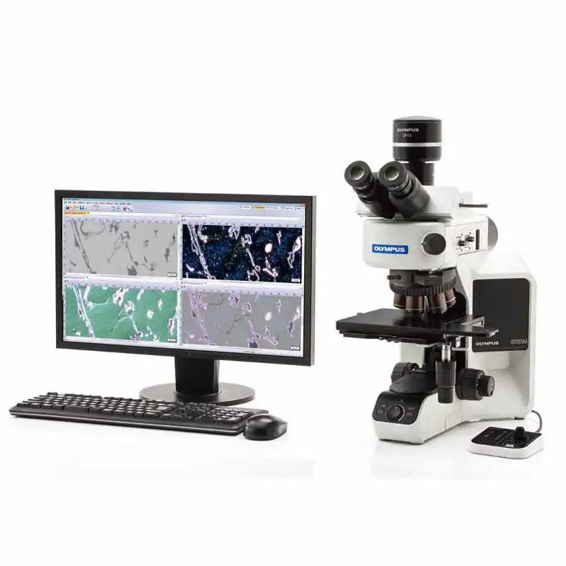
 BX53M_BXFM_Brochure_CN

 中文
中文 English